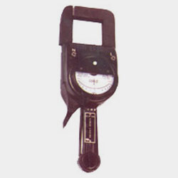
CLIP-ON POWER FACTOR METER
APPLICATION
Measurement of power factor in AC system on L.T. Circuits having higher current load without interrupting circuit.
These instruments are very simple and convenient to operate as described below:
1. SINGLE PHASE CIRCUITS :
Connect potential between Neutral and line and clamp over ‘Line’ cable The instrument will read the power factor directly.
2. THREE PHASE CIRCUITS: (4 Wires System)
(a) Balanced Loads :Measure as in ‘1’ above in any of the phase. The instrument will read the power factor directly.
(b) Unbalanced Loads Measure as in ‘1’ above in each of the three phases.
Power factor is the algebraic mean of the individual readings of the three phases.
3. THREE PHASE CIRCUITS: (3 Wires Systems)
Derive a Neutral with the help of a Neutral Box and measure as in ‘2’ above.
SPECIAL FEATURES
- STABLE MEASUREMENTS EVEN UNDER ADVERSE CONDITIONS
- SINGLE HANDED EXTREMELY SIMPLE OPERATION
- MEASUREMENT IN AC SYSTEMS ON L.T. CIRCUITS HAVING HIGHER CURRENT LOADS WITHOUT INTERRUPTING CIRCUIT
- SAFE FOR USE ON BARE CONDUCTORS
- USABLE IN SINGLE PHASE AND THREE PHASE CIRCUIT
- SHOCK AND VIBRATION PROOF CONSTRUCTION
- HIGH CLASS SOLID STATE TRANSDUCER CIRCUIT
- HIGHLY SENSITIVE JEWELED INDICATOR (P.M.M.C.)
- HOUSED IN BAKELITE BODY
- CONFIRMS TO IS:1248-1983
CLIP-ON POWER FACTOR METER
 MODEL: CIE/111 SERIES
Effective Measuring Range : 0.5 lag (Ind.) to unity to 0.5 lead (Cap.)
- MODEL CIE/111A : 10-500A
- MODEL CIE/111B : 150-1000A
- MODEL CIE/111C : 10-20A
- MODEL CIE/111D : 20-70A
- MODEL CIE/111E : 70-150A
- MODEL CIE/111F : 150-300A
- MODEL CIE/111G : 300-500A
- MODEL CIE/111H : 500-750A
- MODEL CIE/111I : 750-1000A
Potential : 230V / (415V through Netural Box)
Note : Measurement Accuracy is not effected by voltage fluctuation within ±10%
SPECIFICATIONS :
- Core – Gap : 55 mm Maximum
- Dielectric Test Voltage : 2 KVAC ( r.m.s. ) for 1 min.
- Insulation Resistance Test : Over 25 ohm at 500v DC
- Scale length : 70 mm (approx)
- Frequency : 47 – 53 H Z
- Dimensions (In mm) : 330 x 99 x 98
- Response Time : Less than 1.8 kg (approx)
- Weight : 1.8 kg (approx)
- Calibration : 50 H 1 AC Supply
- Confirms to IS : 1248 – 1983
- Accuracy : ± 3* (expressed as phase angle)
- Indicator : Analogue, Moving Coil Type Indicating Meter
- Accessories (Standard) : (1) Potential Leads – 1 pair, (2) Operator”s Manual – 1No. (3) Carrying Case – 1N0. Accessory (optional), Neutral Box.
